 Contact
 Send your CV
 +34 96 272 40 01
 info@garciacamara.com

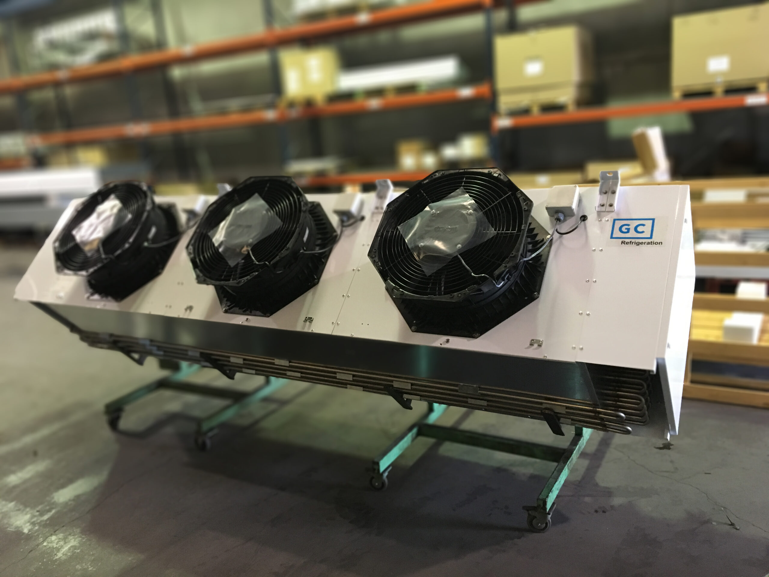
In line with our innovation and sustainability strategy, we continue developing industrial refrigeration solutions based on the use of ammonia (NH₃) in direct expansion and low-charge systems, consolidating our position as a benchmark in energy efficiency and environmental responsibility.
This technology allows for high performance levels with minimal refrigerant quantity, reducing operational risks and facilitating compliance with increasingly demanding safety and emissions regulations.
Design and Execution of Installations with NH₃ in Direct Expansion
The correct operation of direct expansion systems with ammonia (NH₃) largely depends on rigorous technical design and careful on-site execution. Below, we outline the key aspects to ensure system safety, efficiency, and reliability:
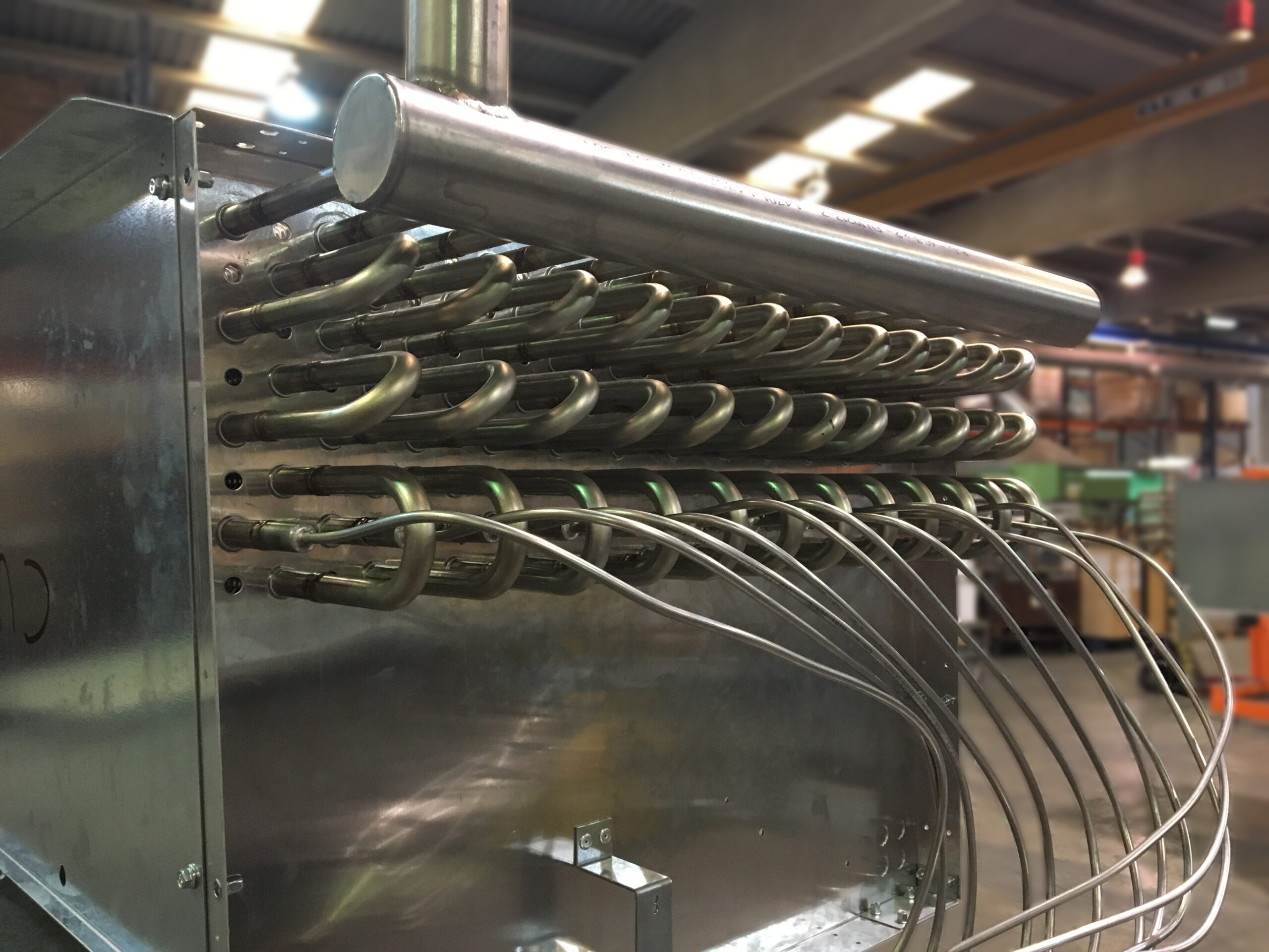
- Welding with Inert Atmosphere
During the welding process of refrigeration lines, it is essential to use an inert atmosphere (N₂ or Ar) inside the tubes. This prevents scale formation from oxidation, which can cause blockages and failures in valves and system components. - Sizing for Maximum Mass Flow
Liquid and suction lines must be sized considering the highest possible mass flow, which occurs under conditions of minimum discharge pressure and maximum suction pressure. This scenario represents the point of greatest hydraulic demand for the piping. - Calculation of Diameters and Number of Lines
It is essential to calculate the number of lines and their respective diameters, ensuring that:
- Fluid velocities remain within the optimal range for oil entrainment and thermal stability.
- Pressure drops are controlled and remain within the limits defined in the design, under any operating condition.
- Routing of Vertical Pipes and Traps
Vertical ascending pipes must:
- Have a trap at the beginning (at the base) to ensure correct liquid entrainment and consequently promote oil recovery in the system (this oil must be miscible with the refrigerant).
- Discharge at the top of the return header, preventing oil from flowing back down into the ascending pipes.
- Drainage of Traps
Drain points must be provided at the lowest parts of the traps, allowing emptying and, if necessary, purging oil from the system. - Slope in Suction Lines
Suction lines must be installed with a minimum slope of 0.5% in the flow direction toward the suction separator, promoting oil return and refrigerant drainage.
The entire system must be designed and installed in compliance with current technical standards, considering safety, maintainability, and energy efficiency as fundamental pillars.